
BLOG
Make Parts Fit Right The First Time With Exact Constraint Analysis
Written by TONY JACKSON, BUSINESS DEVELOPER
It’s a tale as old as time – you build your hardware prototype design in CAD and everything fits perfectly, but when your parts arrive from the manufacturer, some parts are jamming and others are rattling around. What happened?

Often, the underlying problem comes from how the mechanical connections between parts constrain how those parts can move. Through the magic of exact constraint analysis, you can analyze and control the constraints on each part, ensuring that they are located exactly where you want them without jamming or rattling against other parts.
I remember trying to assemble a plastic cosmetic panel to a drawer that was highly overconstrained, with nine screws mating to nine tight holes, none of which aligned on the first sample parts from the manufacturers. I needed to quickly redesign the parts so that the panel would stay tightly located in the right position, while loosening the fit so that the two pieces could be assembled every time. Exact constraint analysis let me get a quick handle on what features were contributing to the problem, then redesign those features while being sure that the panel would still be placed correctly on the machine. The new parts from the manufacturer fit beautifully, allowing us to build 100 of these machines to meet production demand for the quarter.
I learned about exact constraint analysis from Douglass Blanding’s fantastic book, “Exact Constraint: Machine Design Using Kinematic Processing”, which I cannot recommend enough. In this blog post, I’ll give a quick overview of exact constraint analysis in two dimensions from the book’s first chapter, then dive into an example of how to redesign a sheet metal panel to remove an overconstraint condition.
What is a Constraint?
Let us begin in 2D with a sheet of paper on a table. The sheet is free to move in both X and Y and can rotate.
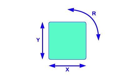
Now imagine pinning one end of a strip of paper to the sheet, then pinning the other end of the strip to the table below. The sheet can no longer move in the Y axis, but for small displacements is still free to move in X and rotate.
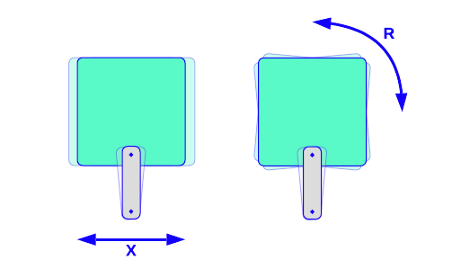
If we draw an infinitely long line through the strip and pins, we can see that any constraint placed along this line would be equivalent in how it constrains the movement of the part. For example, we could place the paper strip on the other side.
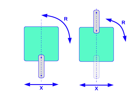
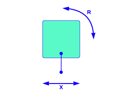
There are many mechanisms that could apply the same constraint to the sheet, such as a pin at the edge with an opposing nesting force. We can generalize these mechanisms as a line segment that represents a mechanism that prevents the sheet from moving along the constraint line.
Adding Constraints
Now let us add another constraint to the left side of the sheet and table. The sheet can now no longer move in X or Y and can only rotate.
By drawing the constraint lines, we can see that the sheet must rotate around the intersection of the constraint lines, called the “virtual centre”.
Next, we move the second constraint down to the bottom edge, parallel to the first constraint. We can approximate that parallel lines intersect at infinity, so the virtual centre will be located infinitely far away from the top edge of the sheet. Rotating about a virtual centre that is infinitely far away is equivalent to translating, so we can see that the sheet is now free to move in X, but constrained in Y and rotation.
Overconstraint
Now, we move the second constraint over to the top side of the sheet and collinear with the first constraint. To give a more tangible example, let’s say that the constraints are once again strips of paper.
There are now two constraints fighting to set the position of the sheet. If the constraints represent fixed-length strips of paper, the strips will experience tension or compression if the sheet is bigger or smaller than specified, e.g. due to manufacturing tolerances.
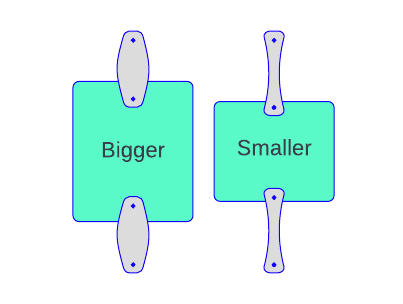
When two constraint lines are collinear, the constraint situation is said to be overconstrained.
Exact Constraint
Let us return the second constraint to the left side of the sheet, then sort out how to constrain the rotation about the virtual centre. We know from the two-constraint example that the centre of rotation will occur at the intersection of the constraint lines, so the third constraint must not pass through the centre of rotation to remove the rotational degree of freedom. Ideally, placing the constraint far away from the centre of rotation and perpendicular to the movement of rotation will create the largest “moment arm” about the centre to resist motion. Let us add a constraint in the bottom-right corner to maximize the distance “d” from the virtual centre of rotation. As the constraint will be resisting rotation, let us also align it perpendicular to a line passing from the centre of rotation to the third constraint.

The sheet is now unable to move in any direction, but there are no constraints that are fighting to set the position of the sheet – the sheet is in a situation of exact constraint.
Note that as we added each constraint, the number of degrees of freedom of the sheet were reduced by one. From this, we can see that the number of constraints + the number of degrees of freedom = the total degrees of freedom.
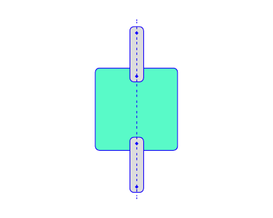
Pin and Hole Joints
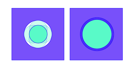
We now draw our attention to redesigning a real-world example: the pin and hole joint. The pin and hole is designed to prevent movement in X or Y while allowing rotation about the pin. The position of the pin in the hole will be set by both sides of the hole. If the pin is smaller than the hole, it will be free to move around. If the pin is larger than the hole, there will be high stresses in the pin and hole from the interference fit.
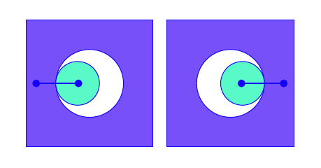
If the pin is only touching one side of the hole, it only has one constraint and is free to rotate or move perpendicular to the constraint. This pin is underconstrained and will rattle inside the hole, giving inconsistent positioning. Alternatively, if the pin is large enough to touch both sides of the hole, it will jam and introduce stresses in the outside of the hole, leading to an overconstrained situation.
The above diagram shows the constraints along one dimension, but these constraints exist for any angle around the circle.
Let’s redesign this interface to better constrain the pin. We know that a perfect pin and hole joint prevents movement in X or Y but still allows rotation, so we expect two constraints to be present in an equivalent exactly constrained design. Let us replace the hole with a V-shaped notch.
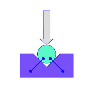
This introduces two constraints, one at each contact point. We’ll need something to prevent the pin from coming away from the V block, so let’s add a nesting force to keep it in place. This could be a variety of things, such as a spring, the weight of the pin, a cam, etc.
The pin will now be consistently located against these two faces without jamming or introducing any play into the system. Removing and replacing the pin is trivial to do and will give very repeatable positioning. This V block constraint is equivalent to the pin and hole joint in that it prevents movement in X or Y while still allowing the pin to rotate.
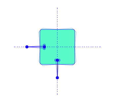
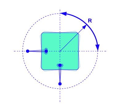
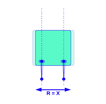
Let’s take another example of a part that we want to locate very consistently to two pins. We know that in 2D, parts have three degrees of freedom, so we will need to add exactly three constraints to fully constrain the part.
We know from the above example that we can get XY constraints from a pin with a V block, so we need one more constraint to prevent rotation. We can extend a face off the side of the V Block to rest against the second pin and provide a third constraint. A nesting force then needs to be applied downwards to keep the part in contact with the pins.
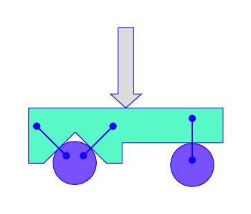
With this design, the position of the part will be very consistent relative to the pins and will not move.
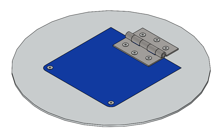
Design Example: Service Panel
Let’s take a look at a practical example of a sheet metal cover for a service panel.
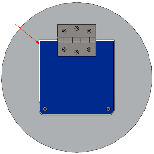
Let’s take a look at the current constraint situation. The edges of the service panel butt up against the housing, so each edge creates a constraint perpendicular to the edge.
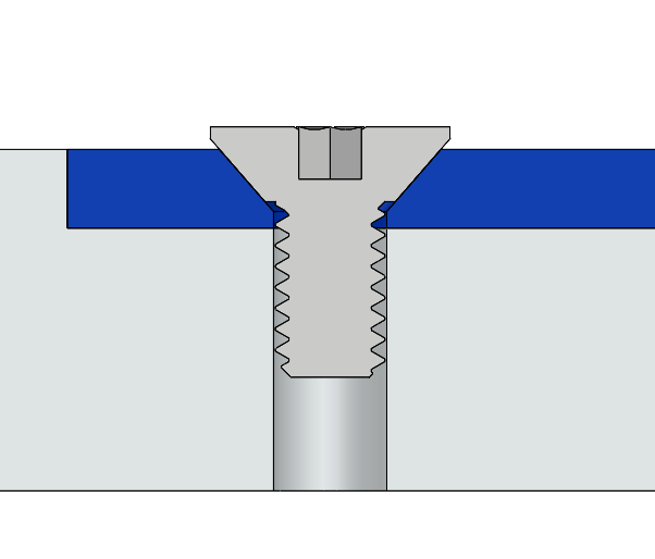
In the top view, these two constraints manifest as perpendicular constraints in X and Y on each flathead screw. The full constraint situation on the sheet metal panel is shown below.
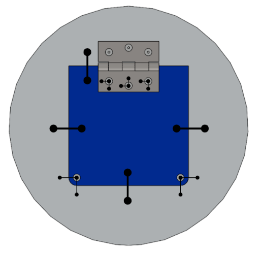
Wow, that’s totally overconstrained – that cover is never going to fit!
Let’s redesign the cover to have exactly three constraints.
To remove the constraint from the panel perimeter, let’s add a clearance gap around the panel so that it does not contact the housing.
If we change the flathead screws to buttonhead screws and leave clearance around the thread for the panel to move, we will remove the constraints from the flathead screws.
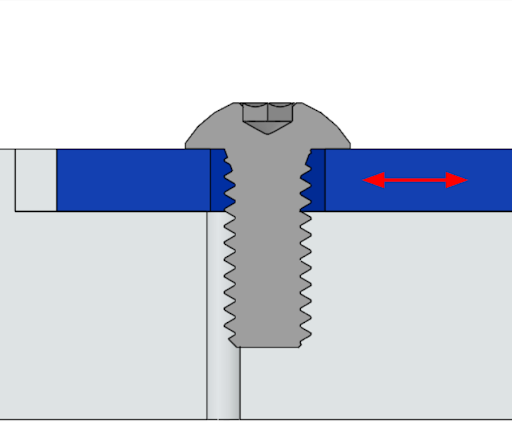
Let’s change all the screws to buttonheads to remove those constraints.
We’ve now removed all constraints from the service panel, so if we stopped here, the panel would rattle around and never align consistently. This loose, rattly, misaligned feel is characteristic of an underconstrained assembly.
To fix the underconstraint problem, let’s add in exactly three constraints. For this particular panel, let’s assume that we trust the lower screws that hold the panel shut to be positionally accurate and well-registered to the opening in the housing.
We can adjust the cutting pattern of the sheet metal panel to add a diamond-shaped hole on one side and a slot on the other. This gives the same three-constraint V and flat design from the previous example.
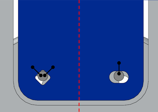
The panel is now exactly constrained! For installation, the assembler can leave the hinge screws slightly loose, then align the panel by letting it be pulled downwards by gravity onto the lower screws. Once the panel is aligned, the hinge screws can be tightened to lock in the panel alignment.
Conclusion
Douglass L. Blanding’s book goes much further into using constraint analysis to understand and simplify complicated 3D assemblies, and also includes examples of various constraints and designs.
Are you fighting manufacturing and assembly issues on your prototypes? Do you want to have an assembly that’s easy to manufacture and goes together correctly every time? Drop MistyWest a line by sending an email to [email protected]. We have experience with design for manufacturing, both at small-to-medium scales with machining, casting, and welding, and high scale manufacturing such as injection moulding. We can help turn your hardware prototype into a product that you can build at scale.